This set of MCQ(multiple choice questions) focuses on the Industrial Automation and Control NPTEL Week 0 Assignment Solutions.
Course Layout
- Week 0: Assignment Solution
- Week 1: Assignment Solution
- Week 2: Assignment Solution
- Week 3: Assignment Solution
- Week 4: Assignment Solution
- Week 5: Assignment Solution
- Week 6: Assignment Solution
- Week 7: Assignment Solution
- Week 8: Assignment Solution
- Week 9: Assignment Solution
- Week 10: Assignment Solution
- Week 11: Assignment Solution
- Week 12: Assignment Solution
You can use Previous and Next button to switch to a different set of questions.
NOTE: You can check your answer immediately by clicking show answer button. Moreover, this set of ” Industrial Automation and Control NPTEL Week 0 Assignment 0 Solution” contains 11 questions.
Now, start attempting the quiz.
Industrial Automation and Control NPTEL Week 0 Assignment 0 Solutions
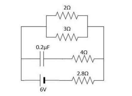
Q1. Calculate the steady state current in 3ohm resistor shown in the figure below. The capacitance value is 0.2µF and internal resistance of the battery is negligible.

a) 1.5 A
b) 0.9 A
c) 0.6 A
d) None
Answer: c) 0.6 A
Q2. Which of the following options is not correct according to Kirchhoff’s Current Law(KCL)?
a) Total current entering a junction is equal to total current leaving
b) Sum of total current at a node is zero
c) We can apply KCL at any point on a straight current carrying conductor.
d) KCL is applicable to closed loops in a network
Answer: d) KCL is applicable to closed loops in a network
Q3. Calculate the mutual inductance of two coils having values 50µH and 100µH connected in series and have a total inductance of 70µF.
a) 40µF
b) 50µF
c) 80µF
d) None
Answer: a) 40µF
Q4. Thermocouples are
a) Active transducers
b) Passive transducers
c) Both active and passive transducers
d) Output transducers
Answer: a) Active transducers
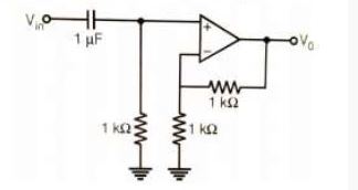
Q5. The op-amp circuit given below is that of a

a) Low-pass filter with a maximum gain of 1
b) Low-pass filter with a maximum gain of 2
c) High-pass filter with a maximum gain of 1
d) High-pass filter with a maximum gain of 2
Answer: d) High-pass filter with a maximum gain of 2
Q6. The digital circuit shown in the figure works as:

a) JK flip-flop
b) Cocked RS flip-flop
c) T flip-flop
d) Ring Counter
Answer: c) T flip-flop
Q7. A MUX circuit shown in the figure below implements a logic function F1. The correct expression for F1 is:

a) (x⊕y)’⊕z
b) ((x⊕y)’⊕z)’
c) (x⊕y)⊕z’
d) (x⊕y)⊕z
Answer: b) ((x⊕y)’⊕z)’
Q8. For the unity feedback control system shown in the figure, the open-loop transfer function G(s) is given as G(s) = 2/s(s+1). The steady state error ess due to unit step input is

a) 0
b) 0.5
c) 1
d) ∞
Answer: a) 0
Q9. Determine the range of K for stability of unity feedback system whose open loop transfer function is G(s) = K/s(s+1)(s+2)
a) K>0
b) 0 < K < 6
c) 0 > K > 6
d) K > 6
Answer: b) 0 < K < 6
Q10. The transfer function Y(s)/U(s) of a system described by the state equations x(t) = -2x(t) + 2u(t), y(t) = 0.5x(t)
a) 0.5/(s-2)
b) 1/(s-2)
c) 1/(s+2)
d) 0.5/(s+2)
Answer: c) 1/(s+2)
Q11. The root locus plot for a system is given below. The open loop transfer function corresponding to this plot is given by

a) G(s)H(s) = k.s(s+1)/(s+2)(s+3)
b) G(s)H(s) = k.(s+1)/s(s+2)(s+3)
c) G(s)H(s) = k.1/s(s-1)(s+2)(s+3)
d) G(s)H(s) = k.(s+1)/s(s+2)(s+3)2
Answer: d) G(s)H(s) = k.(s+1)/s(s+2)(s+3)2
>> Next- Industrial Automation and Control NPTEL Week 1 Solutions
The above question set contains all the correct answers. But in any case, you find any typographical, grammatical or any other error in our site then kindly inform us. Don’t forget to provide the appropriate URL along with error description. So that we can easily correct it.
Thanks in advance.
For discussion about any question, join the below comment section. And get the solution of your query. Also, try to share your thoughts about the topics covered in this particular quiz.
